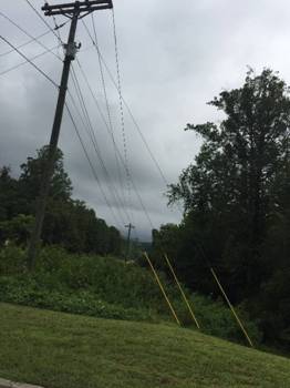
Distribution Line Design – Volume III
Lee Layton, P.E.
Course Outline
The course is divided into five chapters. It begins with an overview of guying and the components used in guying. Pole loading is discussed as well as the expected loads that need to controlled through proper guying. A detailed guying example is provided and the method for determining the proper pole class is explained.
This course includes a multiple-choice quiz at the end, which is designed to enhance the understanding of the course materials.
Learning Objective
After taking this course you should:
- Be able to explain the factors related to guying poles;
- Understand how soil density is classified;
- Know the types of guy wires used in distribution construction;
- Know how to calculate pole loads;
- Be able to define NESC overload factors;
- Understand the NESC requirements for guying;
- Be able to explain when Grade B construction should be used;
- Know how to determine permitted loads on guy assemblies; and
- Know how to determine the pole class required.
Intended Audience
This course is intended for anyone who is interested in the structural design of medium voltage electric facilities used for power distribution.
Benefit to Attendees
This series of courses will give the reader a firm understanding of the mechanical design of electric power distributions lines and provides worked examples of pole loading, conductor tensions and sag, and guying procedures.
Course Introduction
This course is the third volume in a series of three courses on the design of electric distribution pole lines. This volume explains how guys and anchors are installed at distribution line deadends, line angles and at points of unbalanced conductor tensions.
 The first volume in this series discussed how to determine: The loads applied to un-guyed wood distribution poles, a pole’s strength requirements to sustain applied loads, maximum horizontal spans based on pole strengths, crossarm vertical loads, and crossarm horizontal loads. The second course in this series presented the methodology and equations required to calculate distribution line ruling spans and conductor sags and tensions.
Unbalanced conductor tensions occur where the conductor size is changed or where there is an appreciable change in the ruling span. A guy assembly needs to be designed to hold the entire horizontal component of the load being applied on the structure in the opposite direction of the guy assembly. A wood pole is used as a strut and supports the vertical components of all loads on the pole including the vertical forces due to the tension contributed by the guy.
While a pole may have sufficient strength to withstand side strain of angles up to five degrees for small conductors, it is usually advisable to install a guy and anchor to prevent the pole from leaning.
This course describes several typical distribution guy and anchor assemblies and their permitted loads and holding power, respectively. The course also discusses the component parts of guy assemblies and their strengths. Installation guidelines are provided for guy and anchor assemblies.
Within this course is the derivation of the equations required to calculate: loading moments, guy resisting forces for several guying situations, guy loads, minimum guy leads, and required pole class to support vertical loads. Example problems using these equations are also presented.
Course Content
This course content is in the following PDF document:
Distribution Line Design – Volume III
Please click on
the above underlined hypertext to view, download or print the document for your
study. Because of the large file size, we recommend that you first save the
file to your computer by right clicking the mouse and choosing "Save Target
As ...", and then open the file in Adobe Acrobat Reader. If you still experience
any difficulty in downloading or opening this file, you may need to close some
applications or reboot your computer to free up some memory.
![]() You may need to download Acrobat Reader to view and print the document.
You may need to download Acrobat Reader to view and print the document.
Course Summary
In this course we have explained how guys and anchors are installed at distribution line deadends, line angles and at points of unbalanced conductor tensions.
This course was the third in a series of three courses about distribution line design. The first volume in this series discussed how to determine: The loads applied to un-guyed wood distribution poles, a pole’s strength requirements to sustain applied loads, maximum horizontal spans based on pole strengths, crossarm vertical loads, and crossarm horizontal loads. The second course in this series presented the methodology and equations required to calculate distribution line ruling spans and conductor sags and tensions.
We hope this course has given you greater understanding of the mechanical characteristics of distribution line design.
Quiz
Once you finish studying the above course content, you need to take a quiz to obtain the PDH credits.
DISCLAIMER: The materials contained in the online course are not intended as a representation or warranty on the part of PDH Center or any other person/organization named herein. The materials are for general information only. They are not a substitute for competent professional advice. Application of this information to a specific project should be reviewed by a registered architect and/or professional engineer/surveyor. Anyone making use of the information set forth herein does so at their own risk and assumes any and all resulting liability arising therefrom.


