Concrete Forming Systems Options, Considerations, Design
and Cost
Eugene Washington
, P.E.
Course Outline
- Introduction
- Form Options
- Initial form material cost or rental
- Availability of materials
- Usual productivity of form type
- Crew experience
- Liners or surface rustication
- Penetrations
- Blockouts
- Esthetics
- Concrete surface finish quality
- Deflections
- Curing requirements
- Construction Tolerances
- Reuse cycle
- Stripping constraints
- Time constraints for reuse
- Form dimensions
- Complexity of the formed surface
- Pour rate
- Pour Configuration
- Concrete Placing method
- Crane availability
- Crane Capacity
- Site Restrictions
- Access
- Form Design
- Form costs
- Conclusion
This course includes a multiple choice quiz at the end.
Learning Objective
The
Concrete Forming Systems Options, Considerations, Design and Cost course is
designed to provide the reader with a greater awareness of the form selection
process. The goal of this course is
to show how to objectively, efficiently and effectively select, design and cost
forming systems.
Course Introduction
The proper selection of concrete forms is critical to achieving the desired results of esthetics, efficient productions and low costs. This course leads the reader through the numerous considerations and options that are important to the form selection process. This course discusses the important factors and options that are necessary to intelligently select and design concrete form systems. These factors apply to footings, walls, columns and slabs forms and include the method of placing, vibrating, finishing and curing the concrete. The course concludes with an example of wall form design procedures and cost comparisons of two wall form systems.
Course Content
Introduction:
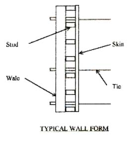
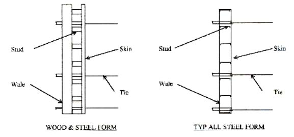
Concrete is one of the most common of construction materials and is found in almost all construction projects. Most concrete is formed. The form is a mold to support and contain the concrete until the concrete has gained enough strength to be self-supporting. The form can be as simple as a 2x4 laid on the ground or the mold for a 500-foot tall statue. Most structural vertical face forms consist of the skin, studs, walers and ties or kickers.
Below
is a commentary on the selection of forms for walls, columns and footings.
The selection of form systems is a function of meeting the desired specified
concrete shape and finish at the least cost.
In order to achieve an optimum decision, the individual should have knowledge
of the various options available, the ability to design forms and the capability
to generate cost comparisons. Every
project has both common and unique features that must be considered before form
systems are selected. There is no one-size-fits-all
solution and every individual has different experiences and preferences.
Below is a detailing of the thought process that all experienced construction
people go through when considering form selection.
How formalized the process of selection is a function of the relative
importance of the decision and the time allowed to make a decision. For instance, a single wall or footing of only
a few square feet doesn’t justify a lengthy study. In fact, such a decision may be left to the
construction crew with excellent results. The
other extreme is a form system may be required to form hundreds of thousands
square feet in hundreds of pours. Such
a decision has a major economic impact and the process of selection should be
detailed in a formal written manner that should examine several alternatives.
Each
form method has a wide range of application and those applications overlap with
different systems to the extent that several form methods may be acceptable
in a project and the choice may be dictated by personal preference, availability,
schedule constraints or specification requirements.
Product suppliers all have manuals that detail their products and offer
excellent suggestions on application. Some
manufactures of forms offer comprehensive support services that include design,
lift drawing and assembly instructions for the use of their forms. I recommend that a library of form products be accumulated. I often refer to my references for design solutions.
From Systems: Here a sampling of the types of forms available, it is by no means complete.
|
EFCO Plate Girder |
Gates |
|
EFCO Lite |
Symons Hand Set |
|
EFCO Redi-Radius |
Symons Vera-Form |
|
EFCO Super Stud |
PLC Core |
|
Patent Mod-U-Form (handset) |
Perri |
|
Patent Gird-R-Form |
All Wood, Snap Tie |
|
Patent Heavy Duty |
Wood and Steel |
|
Custom Modular Forming |
Wood and Aluminum |
Regardless
of the form system selected, the production costs are strictly a function of
logistics. In order to achieve high productivity the crews
must have all the materials and tools readily available. The form system must be as simple as possible
to assemble, set, align and strip. Crews
should be thoroughly trained in efficient and safe form handling methods.
An optimum crew size must be decided.
If the crew is too large, excess idle time will result. If the crew is too small excess cycle time
and even unsafe, inefficient practices will occur because there not enough people
to efficiently handle the form.
Considerations:
There is a long list of forming methods to select from for any given lift of concrete. This selection depends on the factors listed below and must be considered in order to produce an efficient, economical form design.
|
1 Initial form material cost or rental |
13 Reuse cycles |
|
2 Availability of materials |
14 Stripping constraints |
|
3 Usual productivity of form type |
15 Time constraints for reuse |
|
4 Crew experience |
16 Form dimensions |
|
5 Liners or surface rustication |
17 Complexity of the formed surface |
|
6 Penetrations |
18 Pour rate |
|
7 Blockouts |
19 Pour configuration |
|
8 Esthetics |
20 Concrete placing method |
|
9 Concrete surface finish quality |
21 Crane availability |
|
10 Deflections |
22 Crane capacity |
|
11 Curing requirements |
23 Site restrictions |
|
12 Construction tolerances |
24 Access |
Form design may be a function of the material already owned. If a contractor owns an all steel form system, that may be the first choice unless other constraints eliminate the form’s effectiveness. Outside rental of commercial forms rent for about $3.00/sf/mo plus freight and assembly. Simple plywood faced 2x4 studded and waled form materials are in the $2.00 to $3.00/SF plus assembly. Assembly of wood forms vary from 5 SF/mhr if no fabrication area is established to nearly 100 SF/mhr for a fabrication plant. Steel forms take 5 to 20 SF/mhr to assemble. Stick built one-use forms requires no preassembly but the set and strip production is relatively low, and the initial material cost can be less than $2.00/SF
2 Availability of materials
In some areas lumber may be very expensive or freight costs to import commercial forms may be prohibitive. If suitable materials are on hand it may be economical to incorporate them into the forms, even though it may not be the most efficient design.
3 Usual productivity of form type
All wood forms with snap-ties at 2 ft centers usually are placed and stripped between 5 and 15 SF/mh. Gang forms of steel or composite wood and steel with multiple reuses and steel rod type ties spaced on the order of 4 feet on centers or greater can achieve set and strip productions of 25 to 50 SF/mh.
4 Crew experience
If a crew is very experienced with a given form system, then there is little or no learning production losses. If such a system is applicable, it may be more efficient to use than a theoretically more efficient method. Crew learning takes about 6 to 10 cycles before full efficiency is realized. The average cost of this learning is on the order 25 to 50% production loss for those first leaning cycles.
5 Liners or surface
rustication
Often
the concrete surface is to have a cast in design or liner that attaches to the
form. The easiest way to attach such
details is to a plywood or board form face.
These details can interfere with the ties.
Snap tie may not be compatible with the required surface design due to
the varying liner thickness. This can
be solved by using she-bolts, taper ties or similar tie methods.
If such ties are selected then consideration should be given to building
a stronger form that allows greater tie spacing.
6 Penetrations
An all-wood form allows the greatest flexibility for accommodating penetrations such as pipe, beams or rebar. Steel forms can be assembled to accept such penetrations with a wood insert. If the owner/engineer will allow cast in sleeves and rebar couplers, all steel forms can be effectively utilized.
7 Blockouts
It is generally easier to attach blockouts to wood faced forms. Most blockouts in concrete are built out of wood and plywood for only one use. The blockouts are usually trapped by the concrete and demolished during the removal process. Blockouts can be designed to be reused by adding special relief features, but those features are usually expensive and difficult to make work properly. If a blockout can be cycled many times, an all steel design that is hinged or sliding can be efficiently used.
8 Esthetics
This consideration can greatly limit the choice of form facing material. Steel faced forms will generally make the smoothest surfaced with the least “bug” holes (surface air or water pockets). HDO and Finform plywood can produce very smooth surfaces at a premium cost. The plywood joints will still appear, but can be minimized by sealing the plywood joint. Coating the plywood with epoxy or fiberglass resin can produce excellent results.
9 Concrete surface finish quality
If the surface is to be sand blasted or otherwise roughened after the forms are stripped, then almost any reasonable form facing can be used. Be careful in using particle board and other nonstructural sheets as they may deteriorate with exposure to moisture and easily fracture when nails are driven close to an edge. Some products are so hard that only predrilling will allow effective nail driving. Forms that are not exposed to view can have lower quality of facing than architectural exposed concrete. The owner may also wish a wood grain appearance or such that dictates a board or sandblasted plywood to achieve the desired texture.
10 Deflections
Deflections
can be a controlling feature of form design and selection.
Allowable deflections as low as 1 in 500 (ratio of deflection to span)
are often specified. This requires a
heavier than normal form or reduced spans and/or slower pour rates. A wall aligned east-west can show an unsightly
shadow pattern of wavy shadows at sunrise and sunset which emphasizes the form
face deflection and stud lines, which in normal lighting can’t be seen at all.
11 Curing requirements
Some specifications require the forms to remain in place for up to two (2) weeks. This is costly dead time if the forms are being rented by the month. It may also require more forms to be fabricated in order to keep crews productive and meet the project schedule. Generally it is best to strip vertical forms as soon as the concrete is safely self-supporting and immediately applying the required curing method. Curing is especially important during hot dry spells since the surface can dry out too quickly with dusting and shrinkage cracks appearing.
12 Construction Tolerances
Steel Forms are the easiest to align and hold in position due to their intrinsic stiffness and the inability to absorb moisture. Wood forms are difficult to align and hold to tolerances of less than ¼” in 10 ft. The use of cheap lumber grades and the drying/absorption of water can seriously warp and twist the lumber. It is best to use seasoned or kiln dried lumber of at least construction grade quality. Lumber that is too dry or knotty will often split during nail driving causing unwanted offsets and weaknesses in the form.
13 Reuse cycles
If
a minor form is going to be used only once, an in place “stick built” form may
be the best solution. There are single wale form hardware systems that allow efficient
construction up to about 8 ft high. If
the form is higher than 8 ft it is usually better to prefab from an ease of
alignment and stability stand point. When
a clean gang form will be used many times (20 plus uses) without modification
an all steel form may be the best option. When
that appears to be the case, a study as to whether to rent or purchase option
should be considered. If a composite
wood face and wood, steel or aluminum studs and steel wales are studied, the
selection of facing can be very important.
Normal BB class form plywood has about a 10 reuse or less maximum life.
Such a form will have to be very carefully handled and cared for in order
to achieve an extended cycle life. Such
care is difficult to achieve on many construction projects, especially if a
specific esthetic concrete appearance is to be maintained.
Corners will become crushed from handling and nails will loosen. HDO plywood and fin form plywood have denser
surfaces that are easier to clean, but the edges are still easily damaged. The only drawback of steel forms is that the
initial cost can be more than wood based forms and any damage is costly to repair.
The shape of wood based forms are easier to modify because steel forms
require adding and removing panels by bolting and debolting to change configurations.
Odd dimensions can cause clumsy fillers to make up the correct pour lengths.
Starting a steel form on a sloped surface is often an expensive effort.
One major advantage of wood forms is they can be configured into any
shape.
If
several uses are anticipated and several thousand square feet of forms are to
be fabricated, then it is worthwhile to build a good fabrication shop.
This shop should be equipped with a radial saw, electric drills, a band
saw, skilsaws and nail guns. Templates
should be made to spot and align studs. Form
that will experience many uses should be screwed, pallet nailed, galvanized
nailed or use nails with glue coating so that they will resist working out when
the form is racked while handling. The
fab shop should be used to assemble the steel forms since the tools and the
flat surface will speed assembly.
14 Stripping constraints
Designing a form to facilitate stripping is one of the most important considerations in selecting and designing a form system. If the form becomes locked between parallel concrete surfaces, such as interior corners, the only option can be to demolish the form in order to strip it. Obviously, this is costly and can damage the concrete in the process. Always, design a method to relieve the form so that it can be easily stripped. This can be corner slider, mid span relief key or a hinge. Some bonding to the concrete is to be expected, but if the form is properly prepared, it will break loose easily with soft wood wedges. Be sure that people are clear of the form when it is released because it can break loose suddenly and fall unless restrained. Be sure there are adequate lifting points built into the form so that the form can be handled without damage, including the impact of stripping.
15 Time constraints for reuse
Even
though a form may appear to have the opportunity to be reused many times, there
are often reasons that more than one set of forms must be fabricated for the
same pour configuration. The project schedule may demand several clones
of the same form. For instance, if the
cycle time for a given form is one week and there are 40 cycles, a single form
would need 40 weeks to complete. If
the schedule only allows 10 weeks, 4 sets of the same form are required.
Another
important issue is crew efficiency. If this same form is 16 feet high by 30 feet
long and on both sides of the pour the area is 16x30x2 = 960 sqft. If the productivity of set and strip is 30sqft/man-hour
the number of man-hour per cycle is 960 sqft/30 = 32 mh/cycle.
A crew of 4 people working an 8-hour shift will set and strip the form
in one day (4x8=32hr). In order to keep
the crew productive, they need to have a week’s worth of forms available, i.e.:
4 persons x 8 hours/day 5 days/week x 30 sqft/mhr = 4,800 sqft of forms. This type of analyses is important because
the crews know that the work is available so that they can develop and efficient
routine.
Form cycle time is usually a sequence like this:
1] Set one wall side of the form
2] Rebar placement
3] Set the other wall side of the form
4] Install ties
5] Align the forms
6] Place concrete
7] Cure concrete as required
8] Strip the form
9] Clean, repair the form
10]
Reconfigure form if needed.
16 Form dimensions
Forms
are required to be set in an unlimited number of shapes and sizes.
A low footing form is usually a light handset or wood forms staked and
externally braced. A tall form, i.e. over 20 feet high, becomes a major wind sail, scaffold and alignment
bracing concern. Steel forms lend themselves
to such applications better than all wood forms. Heavy wood forms with steel or aluminum vertical
Wales can be effectively used in high lifts. If the form must progress upward in a series of floors or lifts,
steel forms are easier to support and align than all wood forms when they are
being raised to the upper lifts. A small
form of just a few feet on a side doesn’t usually justify the use of a heavy
steel form that requires a crane to move.
17 Complexity of the formed surface
If the form is straight or curved with few offsets and corners such as pilasters, turns nor abruptly varying thickness, then steel may be the efficient choice. Wood forms can be made to almost any complex shape, including double curvatures at reasonable cost.
18 Pour rate
Pour
rate, or how fast a form is filled with concrete can be a very important issue.
The specified time that is allowed from batch to placement in the form
is on the order of 1.5 hours. Considering
delivery time for a transit mixer truck, it is usually advisable to plan to
empty the truck in no more than one-half of an hour. The supply company may have a jobsite time
limit stipulation that requires standby time be paid for the truck after a short
period allowed for discharging the concrete. A wall pour 27 feet long and 1 foot thick uses only 1 cyd of concrete
per vertical foot of height. Unless
short transit mixer loads are used, the form should be designed to accept at
least 10 ft of concrete pour rate per hour. Another solution is to have more than one such
pour scheduled simultaneously so that an 8 or 10 cyd transit mixer can deposit
a partial load into each form so the average pour rate is held to a reasonable
rise. A crane can handle 10 to 50 cyd/hour
of concrete by bucket. A concrete pump
can vary up to 100 cyd yards per hour with an effective average of about 50
cyd per hour. Most commercial batch
plants are capable of producing 80 to 100 cyd of concrete per hour.
A
very large pour in plan, say 54 feet long by 12 feet wide, contains 24 cyd per
foot. A 4-foot-an-hour pour rate would
require 96 cyd per hour delivery and placing.
Special arrangements with the batch plant and extra cranes and/or pumps
may be required. Massive foundation mats theoretically fill
at less that one foot per hour, but the side forms should still be designed
for a full liquid head of concrete. The
reason for this is that the placement of concrete should proceed from one end
in a set of staggered 2-foot lifts. This
method allows for simultaneous pour, screed, finish and curing operations.
It also reduces the risk of cold joints and reduces the time the concrete
lift must be continuously manned. But
what happens is in any given stretch the form will be filled to the top in less
than an hour.
ACI (American Concrete Institute) publishes some excellent books on formwork. They generally recommend a maximum wall pressure design of 1,500 psf. Columns are designed up 3,000 psf because they will be filled in a matter of a few minutes. It is recommended by the author that most forms be designed for no less than 750 psf or liquid head, whichever is less. The form should be stiff enough to resist the impact of concrete pouring and the unbalanced loadings that can occur during placement operations.
19 Pour Configuration
Concrete pours generally fall into the following configurations or shapes:
1]
Slabs. These are usually less than 2
feet deep and cover large surface areas in relation to their thickness.
Usually these forms are staked and or kicked because through ties are
not efficient or effective. One face
of the form will have a full head of concrete before concrete reaches
the apposite side. That means there
is no countering force to resist the load being applied at only one end of the
tie.
2]
Footings or blocks. These can have the same unbalancing load problems as slab pours
for tie loading, but can be deep enough that external kicking is a major concern.
If the block is not so large that the concrete can be placed in about
2 foot lifts over the entire area of the pour and fast enough so that no cold
joints are caused, then a combination of light kicking and through ties can
be very effective. If the ground is stable enough, it can be cut
vertically to eliminate forming and hand backfill operations.
3]
Walls. Walls are designed in all different
shapes and sizes, so this is where the most options are available.
The same tie load balancing problems can occur as in blocks, but for
different reasons. When this unbalancing
occurs, the form can bulge out of alignment, open the form joints and even collapse.
At the intersections of two walls the tie near the corner will have a
different load contribution from each form face.
There are several ways to solve this loading differential.
One way is to run a long tie along the axis of the intersection wall
and tie to the opposing form on the far side.
Another solution is to make connection between the forms at the corner
strong enough to absorb the unbalanced portion of the load.
A third method is to place an external kicker to take the unbalanced
portion of the load. The forms should
be stiff enough and temporarily braced to resist wind, pouring impact, and hold
alignment during the pour. Often such
bracing will be adequate to resist minor tie unbalanced loads. Wall pours are
usually designed for pour pressures between 750 and 1,250 psf. Low wall forms can be designed for a liquid
head of the concrete. Be cautious designing
forms for pour pressures of less than 750 psf. They will tend to be so flimsy that they will
not hold alignment during the pouring operation. Also, there may be insufficient reserve strength if the pour rate
is faster than designed or some other reason the pour pressure is caused to
exceed the design of the forms. Forms
that are designed for over 1,250 psf will be heavy and/or the ties spacing will
be reduced. Often the added cost to
fabricate, place and strip such forms will exceed any saving in pour costs.
Often
walls do not have a constant thickness. An example is earth retaining walls are commonly
tapered from top to bottom and will vary with different wall heights.
This will require multiple lengths of ties.
Snapties can be ordered in varing lengths, but it takes special effort
to make sure each tie is installed in its proper row.
Usually it is better to use threaded rod with she-bolts or taper ties
with a vertical wale or strong back so that the top and bottom need to be aligned.
The middle ties are then only lightly snubbed so the form is not bowed inward.
4] Columns. Columns are also found in any combinations of shapes and sizes. Heavy bridge piers that are either round or rectangular are often best formed with steel forms. This is because columns are poured at very high pours rates to reduce pour costs. ACI recommends pour design pressures up to 3,000 psf for columns. The steel forms are usually bolted into a box or round tube so that bracing, ties and alignment efforts are minimized. The options for smaller building type columns include laminated paper one-use tubes, banded wood, clamped wood, steel round or square, and fiberglass tubes.
20 Concrete Placing method
Concrete is commonly placed in a form by the following methods:
The
reason that the placing method is taken into account is that the form may have
a slow pour rate or it may be filled very quickly.
There is no point in designing a heavy form when a much lighter one will
do. On the other hand, too light a form
will be subject to over stressing and can even burst.
1]
Tail gating. This is where the concrete is discharged directly from the transit
mixer truck chute into the form. The
form must be substantially lower than the truck discharge so that the chute
will slope at an angle of 30 degrees or more.
If a low slump concrete (2” or less) is used or the chute angle is too
flat the concrete will not flow. Then
the concrete must be pushed down the chute with a shovel. That will greatly reduce the pour rate. The chute length is segmental and usually no
more than 20 feet in total length. This
is the fastest and most cost effective method of placing concrete, but is limited
to footing, slabs and low walls that are easily accessed by the transit mixers.
2]
Bucket and crane. This is a common method that is used if a crane is readily available.
The pour rate is limited by the swing and dump cycle of the crane.
Usually, a crane can deliver 10 to 40 cyd/hr depending on bucket size
(3/4 cyd to 2 cyd). For mass pours bucket
of 4 to 10 cyd have been used, but their use is limited to dams and such massive
concrete structures and where large cranes are being employed. Try to spot the crane to minimize booming up
and down, as booming slows the crane delivery cycle.
3]
Concrete pump. This is a popular method
because it frees up the crane from pouring operations, eliminates the need for
tremie hoppers and chutes in the wall forms and can deliver concrete to places
that can not be accessed by crane or trucks.
The pour rate is usually on the order of 30 to 100 cyd/hr.
4]
Belts. Belting is a very effective way
to place concrete in major slabs and blocks.
Belts will place concrete that cannot be pumped or even bucketed.
A belt will deliver low slump, large aggregate mixes that are often used
in dams. Belts can deliver to places
that are impossible to service by crane. The
pour rate is limited only by the batch plant or the ability of the crews to
consolidate, screed and finish the pour.
5]
Miscellaneous. Concrete can be placed
by truck, wheelbarrow, buggy or even loaders and backhoes.
When concrete is delivered in large unit quantities such as dump trucks
or 8 to 10 cyd buckets, impact on the form can be a concern.
One way to reduce impact is to deposit the concrete away from the form
and slowly flow the concrete to the form.
It
should be noted that the pour rate can be controlled by the effective vibration
time. Often the pour rate will exceed
the ability of the vibration effort to consolidate the concrete.
When this occurs, rock pocks and an excess of bug holes will appear. Rock pockets and voids happen when the vibrator
is not being placed in the concrete deep enough, long enough or a spot is missed.
Bug hole (small voids in the formed surface about ½” or so deep and around)
are the result of the vibrator not being left long enough in one spot to work
the air and water bubbles out of the concrete.
Bug holes can be eliminated by vibrating until no air is seen escaping
from the concrete at the form face. If
the specifications require a very smooth finished surface, sometimes the sack
rub portion of the finishing procedure can be eliminated by a through vibration
effort. External vibrators can be effectively used
to eliminate bug holes and rock pockets.
Steel forms or heavy forms that allows for large tie spacing will assist with vibration effort because the vibrator must be pulled all the way out of the form many fewer times than a light weight form using ties at a much closer spacing.
21 Crane availability
If there is no crane readily available or a crane must be rented, it may be better to consider a very lightweight form or panels that can be easily manhandled. Crane utilization and cost should be considered in form selection. If a crane is idle most of the time waiting to handle a limited number of forms it will significantly increase the real total cost of the form. While this may be unavoidable in some cases, it is prudent to look for useful work that the crane can do to reduce idle time. This work may include flying in prefabricated mats of rebar to reduce the form cycle time. The crane can place the concrete in lieu of pumping. The crane can even be put to work on unrelated activities such as claming footing excavation or handling backfill material which is usually performed by other equipment. Even though those secondary operations are not as efficient as the proper equipment, it will reduce overall costs because the crane and/or operator is put to productive use and reduces the cost of other equipment.
22 Crane Capacity
A heavy all steel form 50’ x 20’ high can weight as much as 30,000 lbs. If a large crane isn’t available the form will have to be set in smaller panels, which reduces form production. The same form in wood and steel Wales will weigh about 10,000 lbs. Therefore, a much smaller crane would be needed to handle the wood form. The crane capacity becomes an important issue especially when long reaches are required or the project is serviced with a tower crane. The long form as described will generally require a spreader beam to lift the form. Spreader and rigging weight must be included when considering crane capacities. Using aluminum beams can significantly reduce form weights.
23 Site Restrictions
A confined site may require long crane reaches or even eliminate crane access. Other obstructions, such as power lines may limit crane operations. Steep terrain will limit where cranes can be placed. High lines have been used in mountains and canyons to deliver forms and concrete. There may be very limited space to store and rework forms. A form used to climb a tower should be designed to minimize cleaning and damage so that it will require a minimum number of transfers from the ground to the tower and back.
24 Access
Forms in existing buildings will require special handling considerations such as door opening size and manhandling in and out of the building. Sometimes forms that are easily set can then become trapped behind or under the concrete and rebar the form molded. Such a situation can occur when the new concrete is formed very close to an existing structure. This type of situation may cause the form to be designed for stripping as the controlling feature.
Design of forms
Once
all above has been given its due consideration, brief or formal.
The selection process can proceed. Usually
it is best to limit the number of form systems on a project.
Too many different form types cause procurement problems and the crews
will not have the opportunity to become fully proficient with all the different
systems.
The
design effort is greatly facilitated by form design programs.
The author has written several programs for various form configurations. This allows the ability to optimize several options quickly. Below is the comparison of a composite form
with a plywood skin, lumber studs, steel channel Wales and shebolt ties -Vs-
an all steel form
Lets assume we have a series of multiple pours for a retaining wall that is 24 ft high and 50 ft long and 1.5 ft thick. This pour contains 67 cyd (50’x24’x1.5’/27 = 67 cyd).
The
form area is 2,400 SF (50x24x2 = 2,400 ft)
We
will assume the form can be cycled every two (2) days for the steel form and
three (3) days for the wood form. The reason for this is the production for the
steel form is assumed to be 40 SF/hr. The
steel form can be placed and stripped in 60 mhrs. A crew of six (6) people can complete the cycle
in 10 hours (2,400 ft divided by 40 SF/mhr times 6 people = 10 hours).
If the rebar is flown into the form in prefabbed mats, assume three (3)
hours is required to place the rebar. This allows three (3) hours to pour out of
two (2) work days of 8 hours each (form at 10 hr + rebar at 3 hr + pour at 3
hr =16 hr = 2 days times 8 hr/day). Assume an over night cure allows the form to
be stripped first thing next morning after the pour.
Assume
the wood form can be cycled at 25 mhrs/SF. This requires 96 mhrs to cycle the
form. If the same crew of six (6) people
are used, it will take them 16 hours or two (2) days to cycle the form (2,400
SF divided by 25 SF/mhr times 6 people = 16 hrs). This leaves one (1) full day to rebar and pour
the form. If the same three (3) hours
are used to place the rebar, then 5 hours can be allowed for pouring. The pour rate for the steel form is 24 ft high
divided by 3 hours or 8 ft/hr. The wood
form pour rate is 24 ft high divided by 5 hours or 5 ft/hr.
The rate of pour of the steel form is about 22cyd/hr (67 cyd / 3 hr = 22 cyd / hr)
The rate of pour for the wood form is about 13 cyd (67 cyd/5 hr = 13 cyd/hr)
Both pour rates are well within a crane’s ability to deliver concrete by bucket to the form.
Below is an Excel spreadsheet that is actually used to design forms:
| Below is a sample design: | |||||||||||
| Steel Form Pour Pressure: | steel form | ||||||||||
| R = POUR RATE, FT/HR | 8.00 | Since the pour pressure is 1,090 psf (use R>7'/hr), | |||||||||
| T = CONCRETE TEMPERATURE, DEG F | 70 | a heavy duty steel form can be used. | |||||||||
| W=POUR PRESSURE, R<7'/hr=150+9000R/T | 1179 | No further design check is done because the form | |||||||||
| W= R>7'/hr=150+43400/T+2800R/T | 1,090 | manufacturer will provide calculations for the form. | |||||||||
| Wood Form Design Procedure: | |||||||||||
| Wood Form Pour Pressure: | wood form | PLYWOOD PROPERTIES | |||||||||
| R = POUR RATE, FT/HR | 5.00 | Thickness | 5/8 | 3/4 | |||||||
| T = CONCRETE TEMPERATURE, DEG F | 70 | Sx | 0.360 | 0.456 | |||||||
| W=POUR PRESSURE, R<7'/hr=150+9000R/T | 793 | Ix | 0.133 | 0.201 | |||||||
| W= R>7'/hr=150+43400/T+2800R/T | 970 | I/Q | 0.557 | 0.687 | |||||||
| PLY-ll | DEPTH | WIDTH | Sx | Ix | I/Q | Fb | Va | E | |||
| inch | inch | inch | cin | in^4 | in | psi | psi | psi | |||
| 5/8 BB | 0.75 | 12 | 0.360 | 0.133 | 0.557 | 2,000 | 75 | 1.6E+6 | |||
| SPAN | W | V=0.5WS | M=PL^2/10 | 12M/Sx | Vp=VQ/BI | D=WL^4/150EI | L/D | ||||
| ft | psf | lbs | ft-lb | psi | psi | in | |||||
| 1.33 | 793 | 453 | 49 | 1,627 | 68 | 0.050 | 320 | ||||
| OK | OK | OK | ALLOW: | 240 | |||||||
| STUD | DEPTH | WIDTH | AREA | Sx | Ix | Fb | Va | E | |||
| inch | inch | inch | sqin | cin | in^4 | psi | psi | psi | |||
| 4x6 | 5.5 | 3.5 | 19.25 | 17.65 | 48.53 | 1,500 | 140 | 1.6E+6 | |||
| M=SWL^2/10 | V=SWL/2A | ||||||||||
| SPACING | SPAN | W | Moment | 12M/Sx | Shear | D=WL^4/150EI | L/D | ||||
| ft | ft | psf | ft-lb | psi | psi | in | |||||
| 1.33 | 4.5 | 793 | 1,687 | 1,147 | 127 | 0.040 | 1348 | ||||
| OK | OK | OK | ALLOW: | 360 | |||||||
| STIFF | top span | ||||||||||
| BACK | NUMBER | DEPTH | WIDTH | WEB AREA | Sx | Ix | Fb | Va | |||
| ][ | each | inch | inch | sqin | cin | in^4 | psi | psi | |||
| [6x8.2 | 2 | 6 | 6 | 2.4 | 8.76 | 26.2 | 22000 | 14400 | |||
| M=SGL^3/33.5 | |||||||||||
| SPACING | SPAN | Gc, conc | 12M/Sx | v= V/A | D=1728SG[X^5+2L^4-L^5-2L^2X^3]/120EI | ||||||
| ft | ft | pcf | ft-lb | psi | psi | in | E | L/D | |||
| 4.5 | 7 | 150 | 6,903 | 9,456 | 5,513 | 0.154 | 29.0E+6 | 547 | |||
| OK | OK | OK | ALLOW: | 360 | |||||||
| V=SGLL/2.5 | Es | ||||||||||
| lb | psi | ||||||||||
| 13,230 | 29.0E+6 | ||||||||||
| STIFF | interior span | ||||||||||
| BACK | NUMBER | DEPTH | WIDTH | WEB AREA | Sx | Ix | Fb | Va | |||
| ][ | each | inch | inch | sqin | cin | in^4 | psi | psi | |||
| [6x8.2 | 2 | 6 | 6 | 2.40 | 8.76 | 26.20 | 22,000 | 14,400 | |||
| M=SWL^2/10 | V=SWL/Aw | ||||||||||
| SPACING | SPAN | W | Moment | 12M/Sx | D=WL^4/145EI | ||||||
| ft | ft | psf | ft-lb | psi | psi | in | E | L/D | |||
| 4.5 | 6 | 793 | 12,844 | 17,595 | 3,964 | 0.073 | 29.0E+6 | 993 | |||
| OK | OK | OK | ALLOW: | 360 | |||||||
| TIE | SPACING | SPAN |
|
P=1.1SLW | Tie Pultimate | ||||||
| A-3 | 4.5 | 6 | 970 | 28,809 | 57,618 | ||||||
| OK | |||||||||||
The
tie is the most critical structural unit of the form and a safety factor of
2 to 1 is recommended for design. If the tie bursts, the load transfer to the
other ties causes the form to literally unzip.
That results in a catastrophic failure of the form. Anyone in the area of the form is at risk from
ejected ties and the collapsing form. The
cost of a major form failure can exceed $100,000. These failures are usually the result of a
combination of factors, such as low tie safety factor, high pour rate, cold
weather and over-retarded concrete.
If
the ties are properly designed, any overloading will show up as excessive deflection
of plywood, cracking or crushing of the wood studs and wales.
When this condition is seen there is usually time to stop or slow the
pour with no risk to the crews and at minimal extra cost.
Now
that the forms are designed, a cost comparison can be made between a wood form
and a steel form. First we will compare a 4-cycle use and then a 40-cycle use. Note that the wood form is lighter and a smaller
crane is used to handle the wood forms. Below is a cost comparison also done in an Excel worksheet:
| Now that a wood form is designed, the cost comparison can be generated. | ||||||||
| First we will compare a small form reuse cycle | ||||||||
| Case 1: | ||||||||
| Number of pours | 4 | each | ||||||
| Assemble Forms | 10 | days | ||||||
| Form Length | 50 | ft | ||||||
| Form Height | 24 | |||||||
| Form Fab Area = | 2,400 | sf | Unit cost | Cost | ||||
| Total Area Formed | 9,600 | sf | ||||||
| Steel Forms costs: | ||||||||
| Freight in and out allowance: | $ 1,000.00 | |||||||
| Rent | 2 | days | 0.90 | mon | $ 3.00 | $ 6,480.00 | ||
| Loss and damage allowance as a percent of rent | 10% | $ 648.00 | ||||||
| Fab labor | 8 | mh/sf | $ 30.00 | $ 9,000.00 | ||||
| P&S Labor | 40 | mh/sf | 240 | mhrs | $ 30.00 | $ 7,200.00 | ||
| Tie Rod costs | $ 0.50 | $ 4,800.00 | ||||||
| Form Weight (one side only) | 30 | psf | 36,000 | lbs | ||||
| Since the crane must be able to lift 20 tons and advance the form (use a 35' radius), a 70 ton cane is selected. | ||||||||
| 70 ton Crane and operator | 0.90 | mon | $ 19,000 | 17,100.00 | ||||
| Pour Crew add an hour for set up | 3 | hr/pour | 4.00 | crew size | $ 25.00 | $ 1,600.00 | ||
| Steel Form Cost: | $ 47,828.00 | |||||||
| Wood Form Cost | ||||||||
| Plywood | 5/8 BB | $ 0.75 | $ 1,800.00 | |||||
| Studs | 4x6 | 3609 | bf | $ 0.80 | $ 2,887.22 | |||
| Wales | [6x8.2 | 8.2 | lb/lf | 8,747 | lbs | $ 0.30 | $ 2,624.10 | |
| Fab labor | 8 | mh/sf | 300 | mhrs | $ 30.00 | $ 9,000.00 | ||
| P&S Labor | 25 | mh/sf | 384 | mhrs | $ 30.00 | $ 11,520.00 | ||
| Tie Rod costs | $ 0.35 | $ 3,360.00 | ||||||
| Form Weight (one side only) | 10 | psf | 12,000 | lbs | ||||
| Since the crane must be able to lift 7 tons and advance the form (use a 35' radius), a 25 ton cane is selected. | ||||||||
| 25 ton Crane and operator | 3 | days | 1.10 | mon | $ 12,000 | 13,200.00 | ||
| Pour Crew add an hour for set up | 5 | hr/pour | 4.00 | crew size | $ 25.00 | $ 2,400.00 | ||
| Wood Form Cost: | $ 46,791.32 | |||||||
| The potential saving by using wood forms is: | $ 1,036.68 | or | 2% | |||||
| Now we will compare a large form reuse cycle using the same forms | ||||||||
| Case 2: | ||||||||
| Number of pours | 40 | each | ||||||
| Assemble Forms | 10 | days | ||||||
| Form Length | 50 | ft | ||||||
| Form Height | 24 | |||||||
| Form Fab Area = | 2,400 | sf | Unit cost | Cost | ||||
| Total Area Formed | 96,000 | sf | ||||||
| Steel Forms costs: | ||||||||
| Freight in and out allowance: | $ 1,000.00 | |||||||
| Rent | 2 | days | 4.50 | mon | $ 3.00 | $ 32,400.00 | ||
| Loss and damage allowance as a percent of rent | 10% | $ 3,240.00 | ||||||
| Fab labor | 8 | mh/sf | $ 30.00 | $ 9,000.00 | ||||
| P&S Labor | 40 | mh/sf | 2400 | mhrs | $ 30.00 | $ 72,000.00 | ||
| Tie Rod costs | $ 0.50 | $ 48,000.00 | ||||||
| Form Weight (one side only) | 30 | psf | 36,000 | lbs | ||||
| Since the crane must be able to lift 20 tons and advance the form (use a 35' radius), a 70 ton cane is selected. | ||||||||
| 70 ton Crane and operator | 4.50 | mon | $ 19,000 | 85,500.00 | ||||
| Pour Crew add an hour for set up | 3 | hr/pour | 4.00 | crew size | $ 25.00 | $ 16,000.00 | ||
| Steel Form Cost: | $ 267,140.00 | |||||||
| Wood Form Cost | ||||||||
| Plywood | HDO | $ 1.25 | $ 3,000.00 | |||||
| Studs | 4x6 | 3609 | bf | $ 0.80 | $ 2,887.22 | |||
| Wales | [6x8.2 | 8.2 | lb/lf | 8,747 | lbs | $ 0.40 | $ 1,154.89 | |
| Fab labor | 8 | mh/sf | 300 | mhrs | $ 30.00 | $ 9,000.00 | ||
| P&S Labor | 25 | mh/sf | 3840 | mhrs | $ 30.00 | $ 115,200.00 | ||
| Tie Rod costs | $ 0.50 | $ 48,000.00 | ||||||
| Form Weight (one side only) | 10 | psf | 12,000 | lbs | ||||
| Since the crane must be able to lift 7 tons and advance the form (use a 35' radius), a 25 ton cane is selected. | ||||||||
| 25 ton Crane and operator | 3 | days | 6.50 | mon | $ 12,000 | 78,000.00 | ||
| Pour Crew add an hour for set up | 5 | hr/pour | 4.00 | crew size | $ 25.00 | $ 24,000.00 | ||
| Wood Form Cost: | $ 281,242.11 | |||||||
| The potential saving by using steel forms is: | $ 14,102 | or | 5% | |||||
The
steel and wood form reversed economic advantage when the reuse cycle increased. While 5% savings does not seem like much, but
many projects are priced with only a 5% or less profit margin. There are other considerations, such as the
wood form took two months longer than the steel form when cycled 40 times. This can be critical to the project schedule
or force the completion into adverse winter weather, further increasing costs.
The
costs are close enough in this example that availability of form materials or
crew preference may be the determining factor.
If the contractor already owns suitable forms, then the rental saving
will cause the steel forms to be economically competitive even for just a few
cycles. The form rent for 40 reuse of steel form is
calculated to be $32,400. That is over
$13.00 per sqft. Steel forms can be
bought for about $25.00 per sqft. If
significant additional use can be foreseen, it may be cheaper to buy the form
since it can be used over and over for many years.
There
is no fixed formula that automatically selects the best form system, but experience
and computer programs to design and cost alternatives are of real value.
Course Summary
Thoughtful form selection and implementation of effective form systems will result in efficient crew productions and achieve the desired finished product with a minimum of effort.Related Links
For additional technical information related to this subject, please visit the following websites or web pages:American Concrete Institute
***
Once you finish studying the above course material, you need to take a quiz to obtain the PDH credits.
***
DISCLAIMER: The materials contained in the online course are not intended as a representation or warranty on the part of PDHonline.com or any other person/organization named herein. The materials are for general information only. They are not a substitute for competent professional advice. Application of this information to a specific project should be reviewed by a registered professional engineer. Anyone making use of the information set forth herein does so at their own risk and assumes any and all resulting liability arising therefrom.